Making of a butterfly pendant
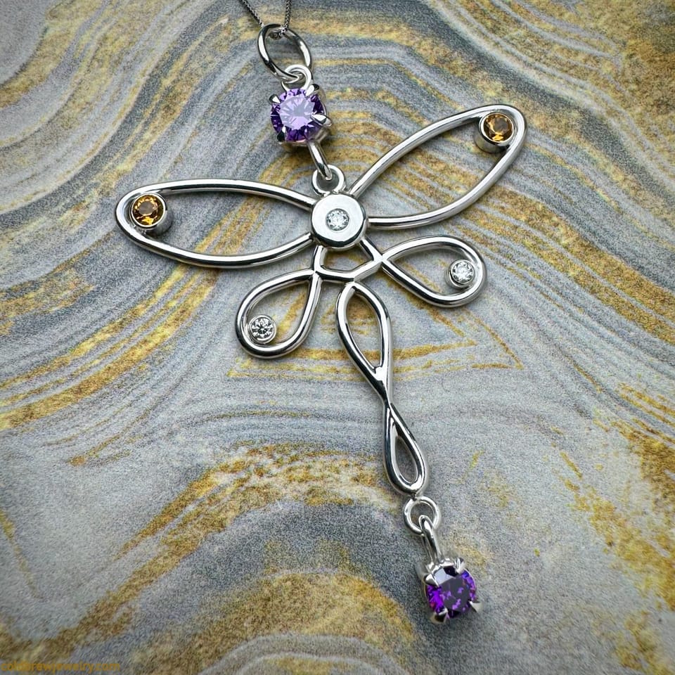
Summer is here, and so are the vibrant colors around us. Inspired by the season, I wanted to create something light, intricate, and colorful. In this post, I describe how I made a butterfly pendant with moissanites, citrines, and CZs in different settings, primarily from sterling silver wire.
Before we continue, I want to mention that I'm not a professional silversmith. These are my learnings as a hobbyist. I'm sharing them for informational purposes only, so use them at your own risk.
I had a few sketches of a butterfly-shaped pendant in my sketchbook. I decided to revisit them and make some tweaks. Here’s what I envisioned initially:
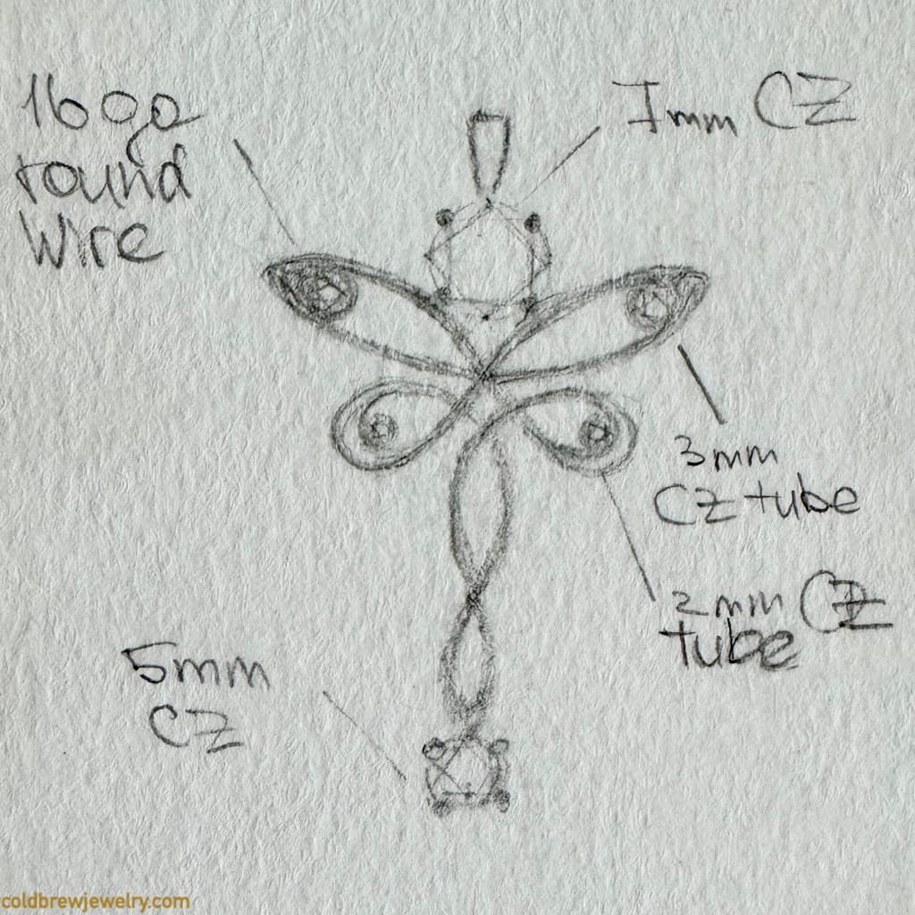
Since I’m still learning Blender, I decided to create a 3D model of the pendant to see how it looks and what I can tweak to improve it. I wanted to use sterling silver for the pendant, so I’d need to choose a 16-gauge wire to make it work. A thinner silver wire wouldn’t be sturdy enough to hold the shape. Ideally, I’d use gold for the pendant. But since this is a training piece, I’ll stick to silver.
My initial idea was to bend the whole shape from one piece of wire and solder it in the overlapping spots. However, after creating a 3D model, I realized it simply wouldn’t work with a 16-gauge wire. Multiple overlapping curves would make the pendant look too thick and clunky.
Another idea derived from 3D modeling was to add a round piece in the center to reduce wire intersections. With a stone set, this piece plays nicely with the upper and bottom stones in the basket settings.
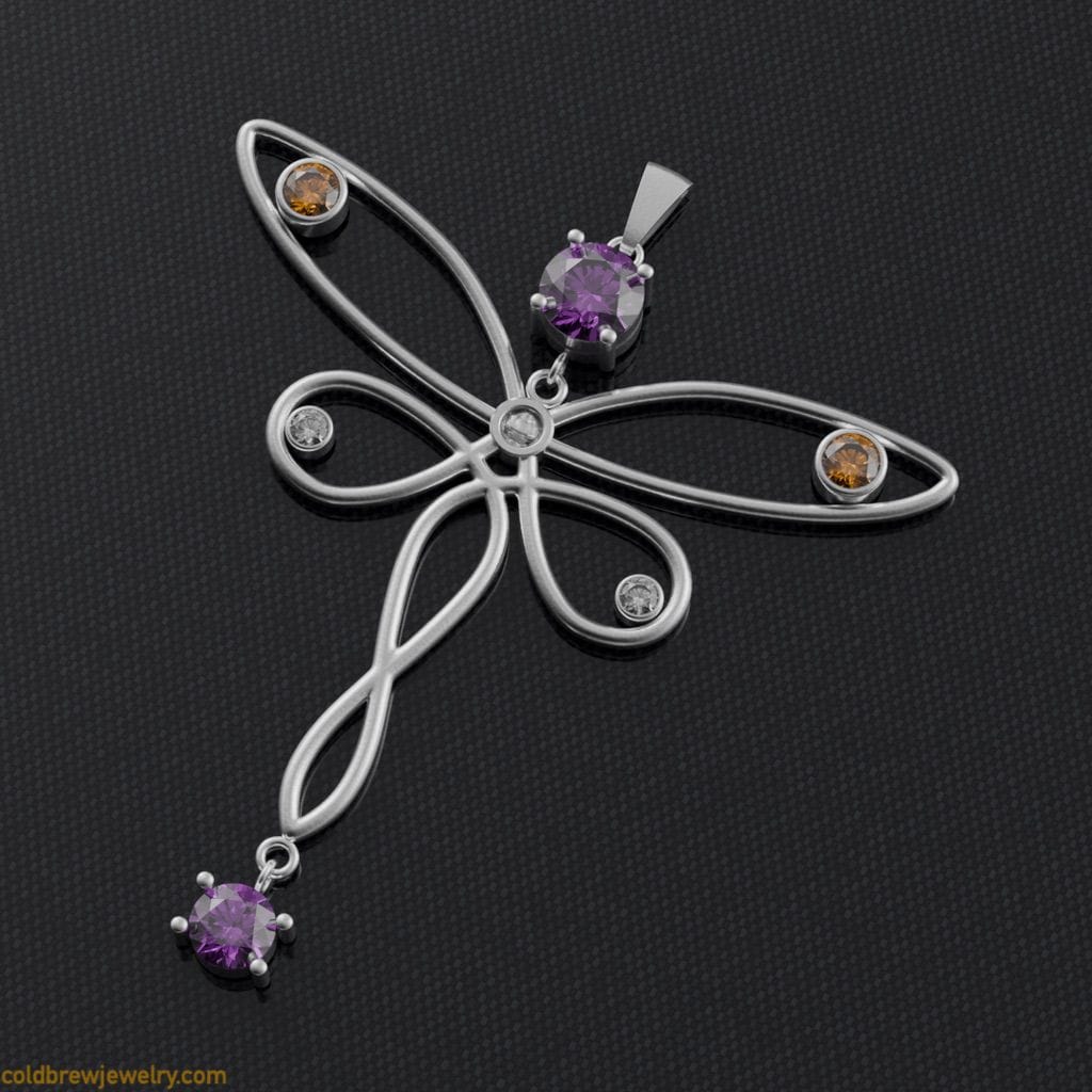
Alternative. Another option is to saw the shape out of a relatively thick silver sheet and then sculpt it with a graver or a bur. This reduces the number of soldering operations to a minimum and makes the structure more sturdy. However, it does change the look.
Architecture
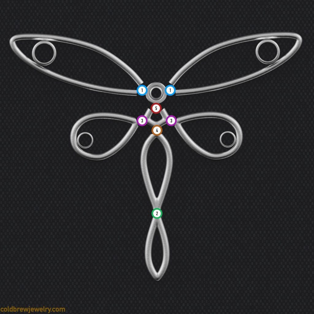
I decided to break down the design into pieces based on the wire intersections and connections.
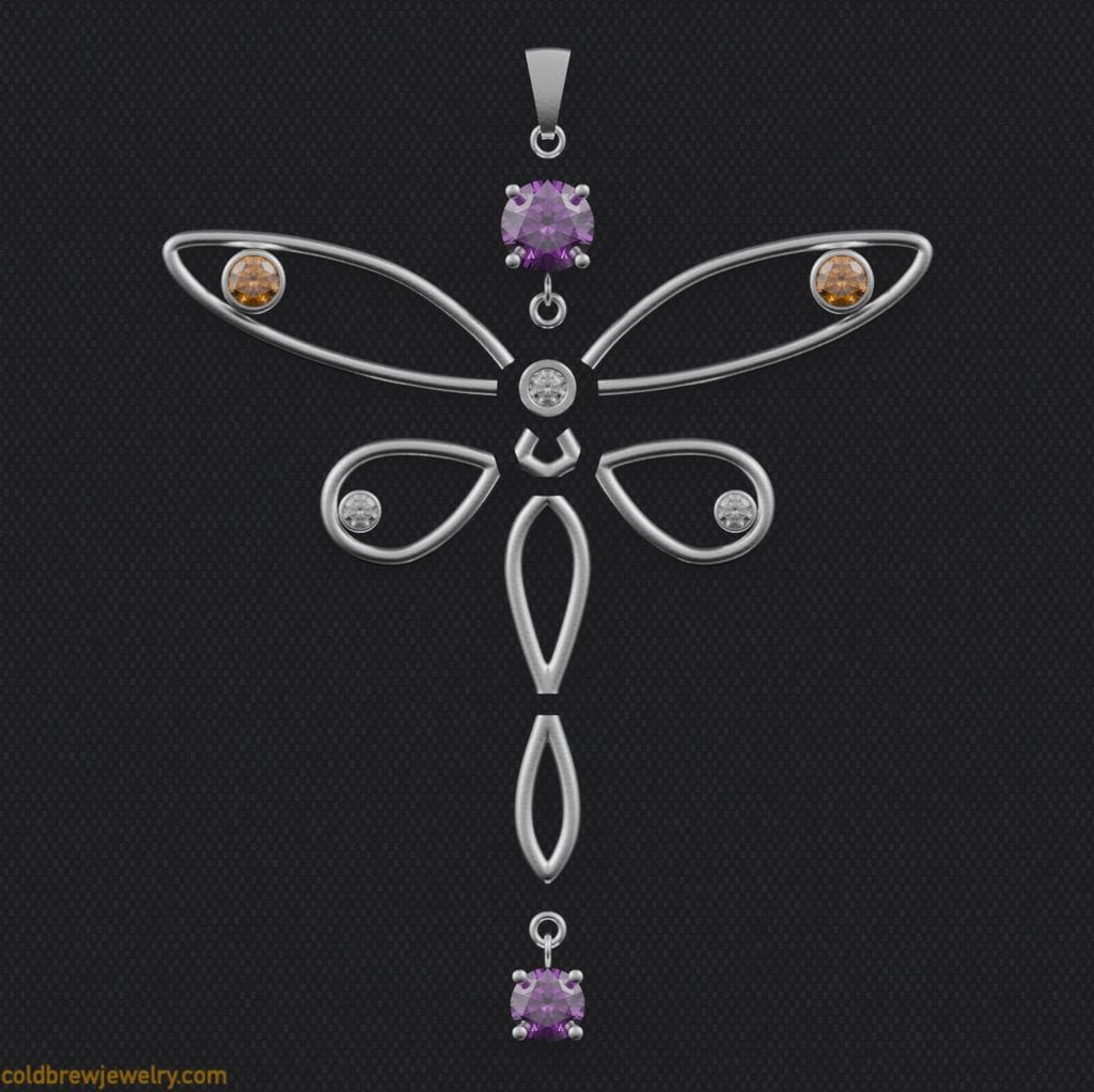
Here’s the list from top to bottom:
- A bail with a jumping (1).
- A basket setting for the upper stone (2).
- A round piece in the center (3).
- Top wings with two tube settings (4).
- Connection piece between bottom wings and the round piece (5).
- Bottom wings with tube settings (6).
- Large segment of the bottom part of the body (7).
- Small segment of the bottom part of the body (8).
- A basket setting for the bottom stone (9).
- Jump rings to connect basket settings to the rest of the piece (10).
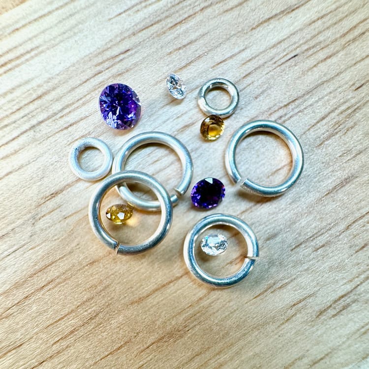
The idea was to solder smaller parts first and then solder them together using holding clay. I also planned to use jump rings to connect basket settings to the body. Two 3 mm citrines would go into the tube settings in the upper wings, two 2 mm moissanites would go into the tube settings in the bottom wings, and a 3 mm moissanite would go into the round piece in the center. The top basket setting would hold a 5 mm purple CZ, and the bottom would have a 4 mm CZ.
When bending wire, I wanted to achieve consistent curvature across the board. I have a set of rods of different diameters from a jumping-making jig. I’d put a rod in a vise and bend the wire around it with my fingers. To make the process easier, I annealed the wire first. Ideally, it’s better to form a large coil from the wire and then anneal it. This way, you reduce the chance of melting it. The drawback is that you need a large enough pickle pot to clean the wire. My pickle pot is small to save some desk space. So, I had to anneal smaller pieces separately.
This is where a 3D model comes in handy to measure the right amount of wire. You can measure the length of the curve and then add some cushion for easier bending.
I used nylon-jaw pliers to form the wire further when needed. It can be tricky because nylon and Delrin are slippery, but the good thing is they don’t mar the metal. You can also use any regular pliers with a piece of leather glued to the jaws. I even have a piece of leather on my desk that I put either in the vise or the pliers temporarily to hold something without leaving marks.
The challenging part of bending was preserving the curvature between different parts to create the illusion of a continuous wire. To achieve that, I created the parts by bending and overlapping the wire and then cutting through the overlap. As I explain below, the trick is to make sure you saw it in the correct order.
Bottom segments
Because the bottom segments are relatively narrow, I used a single piece of wire to make them. First, I made this shape for the bottom part (7, 8):
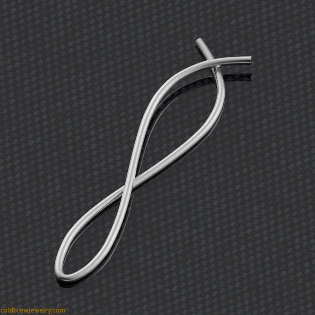
I cut through the topmost overlap first, then the second one in the middle. This way, both sides of the cut stayed steady.
The bottom part of the lower segment (8) was supposed to be a bit pointy. That’s why I made a cut through it and soldered it back. To be honest, it didn’t work that well. The look was still a bit too rounded. But I kept it as is since it’s a minor divergence from the initial design.
Alternative. What I could have done instead is to add another intersection when I was forming the bottom part like this:
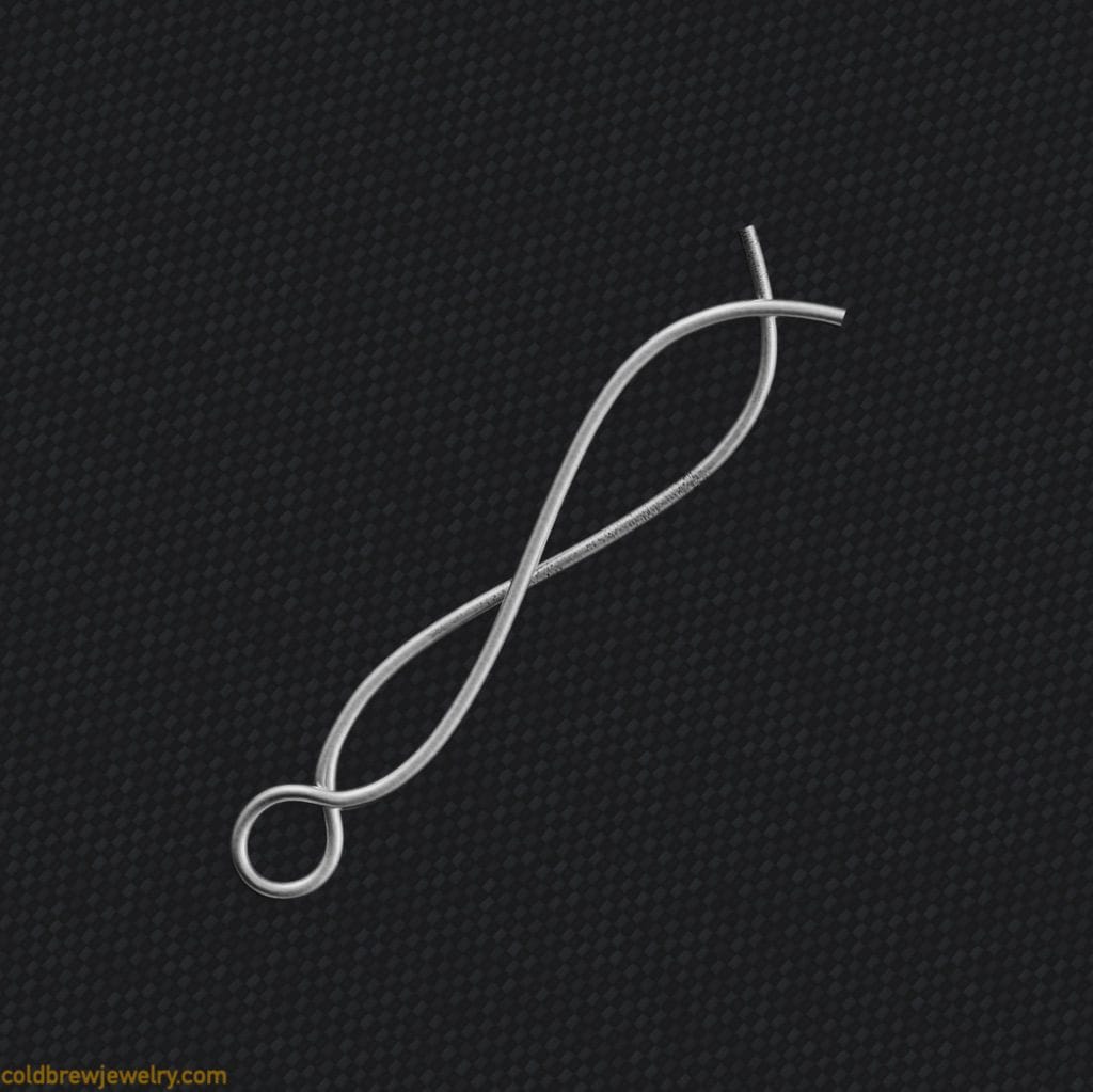
It makes it easier to hold with pliers when sawing. Its proper curvature also allows for that pointy look at the bottom.
After sawing through the first overlap, I realized the cut was slightly off. So when I tried to close the ends together to check, they weren’t correctly aligned. My first thought was to close it tighter and saw through the seam. But when I tried that, I realized that the wires were connected at a very steep angle, and there was not enough tension, which, in turn, meant more room for the saw to wiggle.
Instead, after having two halves of the part, I put them on a piece of sandpaper on a hard, flat surface and sanded them until they were even. This way, the sides were perfectly flat and ready for soldering.
I soldered part 8 and then part 7 using paste solder. This made filing both parts and positioning them to solder them together easier. Again, I used regular hard solder for the second operation. I used my solder pick to adjust everything during soldering.
Alternative . I should have used my titanium soldering clamps to hold the halves of each part together when soldering. By this, I mean not clamping them but lightly supporting the wire on the sides. If you try to clamp a wire while soldering, there’s a good chance that it will collapse when heated.
Connection piece
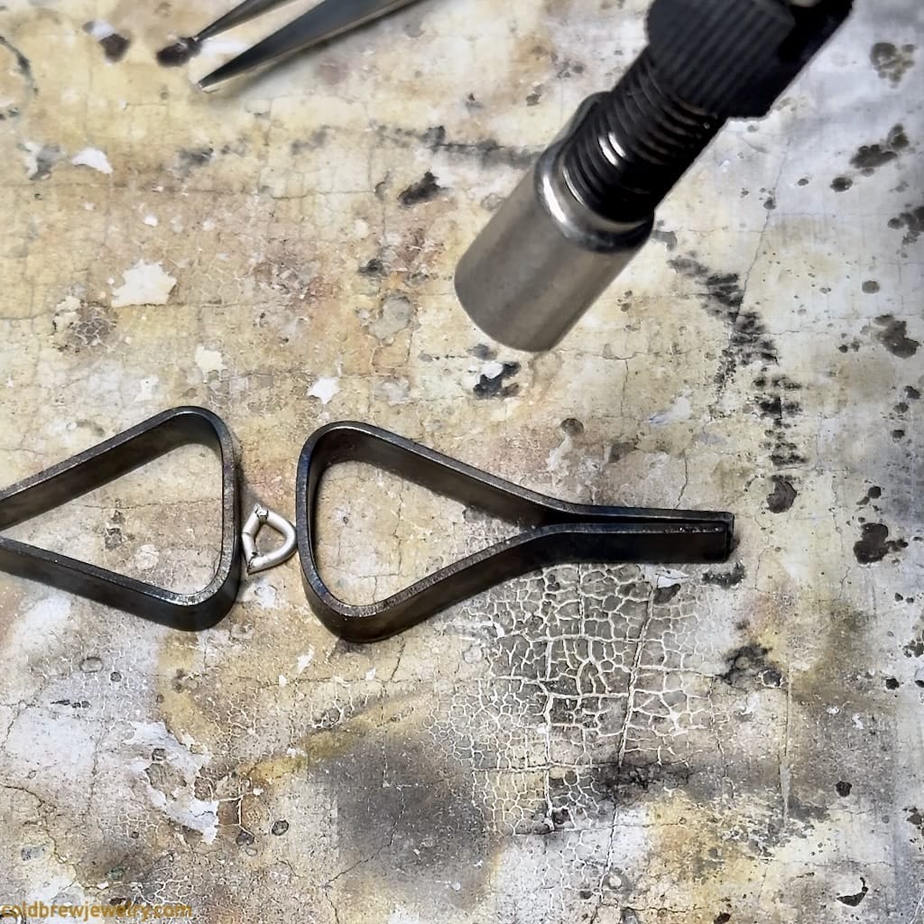
The connection piece (5) was the trickiest to make. To get the curvature right for the two bottom pieces of this part, I took two pieces of wire that I sawed off the bottom wings (see the Bottom wings section below).
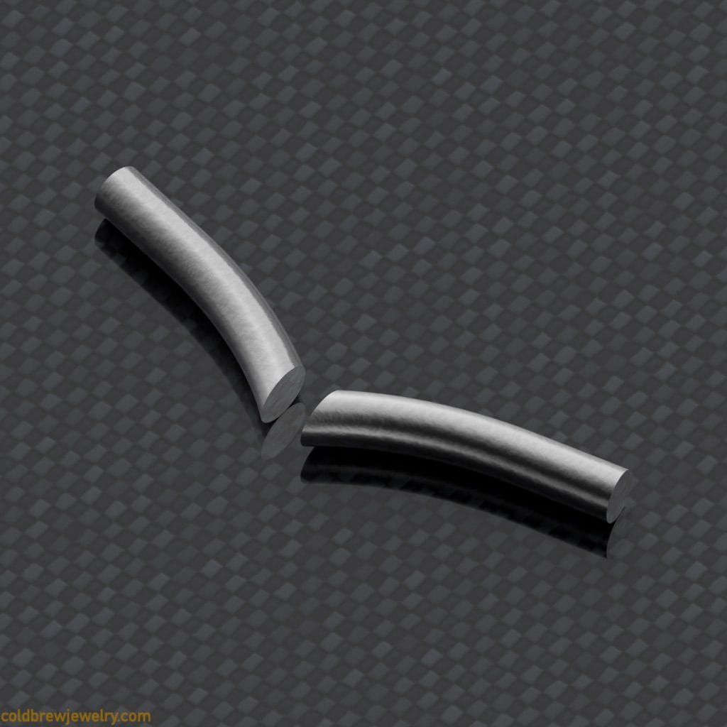
I used a separating disk to file the end of both pieces of wire flat.
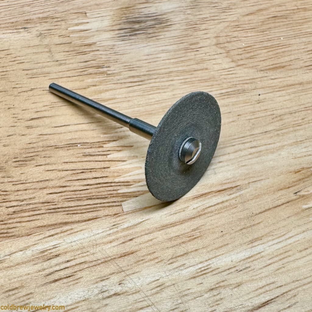
I suggest holding the wire with pliers to avoid injuries because separating discs are pretty aggressive. To make the parts symmetrical, ensure the angle of the flat contact area is the same for both parts. It took me some time to get it right. It helps not to cut the wire to the exact size before soldering but to leave additional length if you need to adjust the flattened area or the curvature.
Next, I soldered them together using paste solder. Paste solder is very helpful when soldering smaller pieces together. It’s easier to apply the right amount. However, it will only fill tight seams. If you use a regular solder, you must be precise about how much you apply it because wires are hard to clean up.
With such small pieces, there’s a temptation to use holding clay for soldering. The drawback is that keeping both pieces leveled in height and rotation can be challenging. Since they are curved, they need to be positioned on the same plane. Sure, you can always use a flat sheet of acrylic to press them lightly into the clay from the top. But I soldered them on my regular soldering board.
Next comes the top of the connection piece, which is just two small pieces of wire on each side. Soldering them separately would be tricky, so I made an arc instead. I used two shaped titanium strips to solder the arc to the bottom part. I usually use them as clamps, but in this case, I just put the wires between them.
Top wings
The top wings (4) are larger than the other parts, so bending them to the proper shape was a bit easier. I used my 3D rendering to get the shape right, but a drawing would work just fine. If I work with a drawing where I need to have symmetrical parts, like the wings in this case, I prefer to take a picture of my pencil sketch and trace it in a graphic editor on my laptop to get the symmetry right. I can also print it as many times as needed to use it as a reference or glue it to a piece of silver sheet when I need to pierce my design.
As you can see in the 3D render, the upper wings include tube-set stones. But I didn’t want the tube to go precisely into the tip of the wing. I wanted to have some space there. Since the outer diameter of the tube was about 3.5 mm, I had to find a slightly smaller rod to bend the wire and create the proper curvature. I used a 2 mm rod in my vise and bent the wire against it. Based on my design, I needed about 40 mm of silver wire for each wing. I added a few millimeters on top just to be safe and cut both wires to the same length after I bent them. But I held off on cutting until I made the round piece in the center.
I cut two pieces of tube about 2.5 mm long for the settings. The miter vise is indispensable here. Without it, it’s hard to make sure the cuts are precisely at 90 degrees. I soldered the settings in place using paste solder.
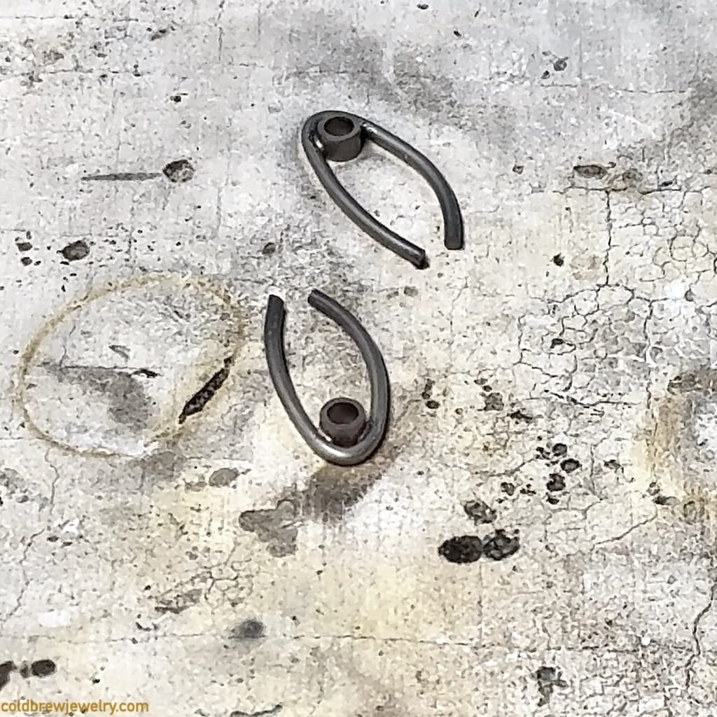
It’s essential to solder them on a flat surface. Even though you can file them later to level out, it’s good to keep the cuts you made using a miter vise so that everything is nice and square.
Bottom wings
I bent the bottom wings (6) around a 4 mm rod. Then, I overlapped the wire to saw through the intersection point. It worked pretty well, and I closed it like a jump ring.
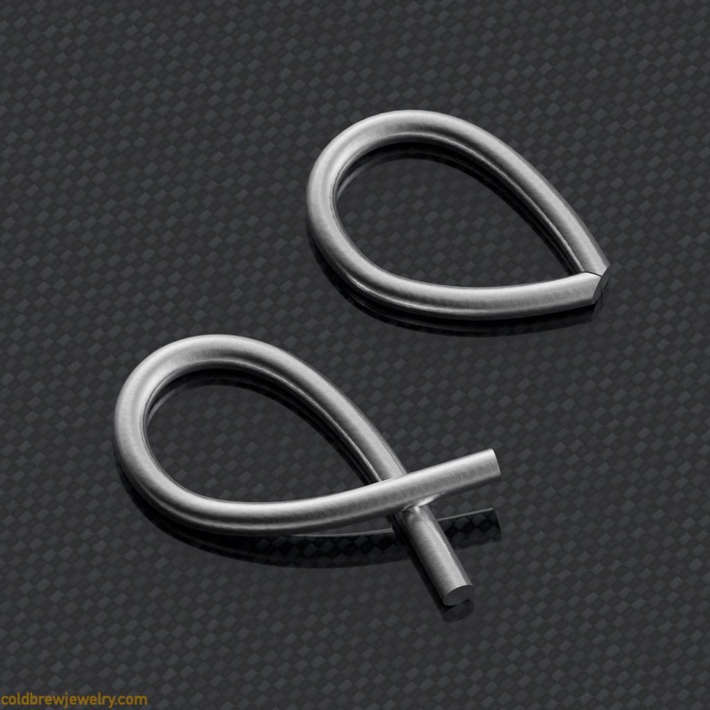
You can always straighten the cut with sandpaper or a separating disc if the cut isn’t even. In this case, even sawing through the joint would have worked. Just be aware of the catch I mentioned above in the section about the bottom segments depending on the shape of the wings.
Then, I cut two pieces of silver tube about 1.5 mm long and 2.5 mm in diameter to create another pair of settings for the 2 mm stones. I soldered them in place using paste solder the same way as with the top wings.
The next operation was to solder the wings to the connection piece (5). I had to file both sides of the connection piece and the wings to create the proper connection.
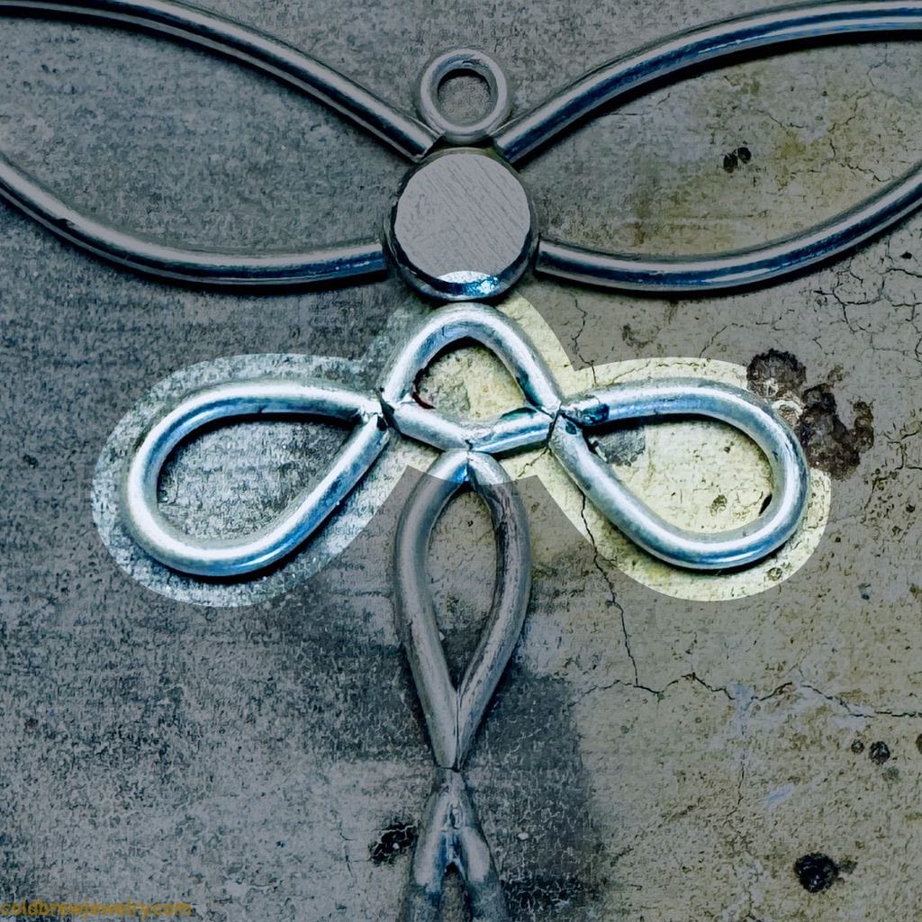
This is where you must be very precise because too much asymmetry will be noticeable. Also, you need to ensure no significant gaps when pieces are placed together on a flat surface.
As you can see in the picture, I marked the parts with color Sharpies to ensure I connected the right parts. Believe me, it’s very easy to flip a piece or use one instead of another when they are virtually the same shape.
I used regular instead of paste solder when soldering multiple connections into one joint to ensure they were sturdy enough. To be honest, paste solder would work perfectly fine because it’s powdered solder mixed with flux. And the total area of contact is small enough when working with wire. One thing to note is that I used hard solder even though I previously used it for the connection piece. The reason is that I knew I would have more soldering operations, and I wouldn’t like to use easy solder. I’m trying to avoid it in general because of the lower amount of silver in that type of solder. But also, when you use hard solder for a specific seam and heat it later, the flow point becomes slightly higher than fresh solder. The difference is minor, so you must be careful and move the flame to the side (not pull it away!) as soon as the fresh solder flows. Anyway, I used my titanium clamps again to hold the connection piece between them to ensure it would keep its shape if I accidentally overheated it.
You probably noticed that I mentioned the clamps multiple times. I love them so much because they are sold as strips that can be formed into any kind of clamp. Titanium conducts heat well, so the clamps don’t act as heat sinks. You can find them at https://knewconcepts.shop.
If you enjoy reading my posts consider subscribing to my newsletter to get some extra content from me each month. And, of course, be the first to know about the new posts 😊
Central round piece
To make the central piece (3), I melted some scrap silver into a ball. I judged the amount of silver needed by eye. I knew I needed a piece about 3 mm in radius and 1.7 mm in height to flush-set a 2 mm stone.
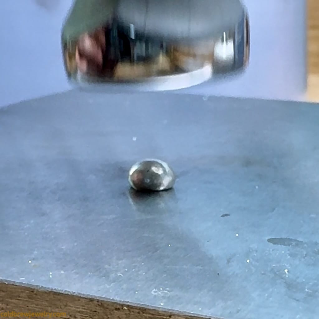
Then, I used my planishing hammer to flatten the ball into a thick circle. I had to anneal it at least once to ensure the metal wasn’t getting too hard and cracking on the edges. I used a file to make it round. I ended up with a 5.5 mm round piece, which was fine and still aligned with the design. At first, I wanted to have a slight chamfer on the top side. But then I realized that making it round instead would match the roundness of the wire. To ensure the piece was round, I was referring to a pattern etched in my bench pin:
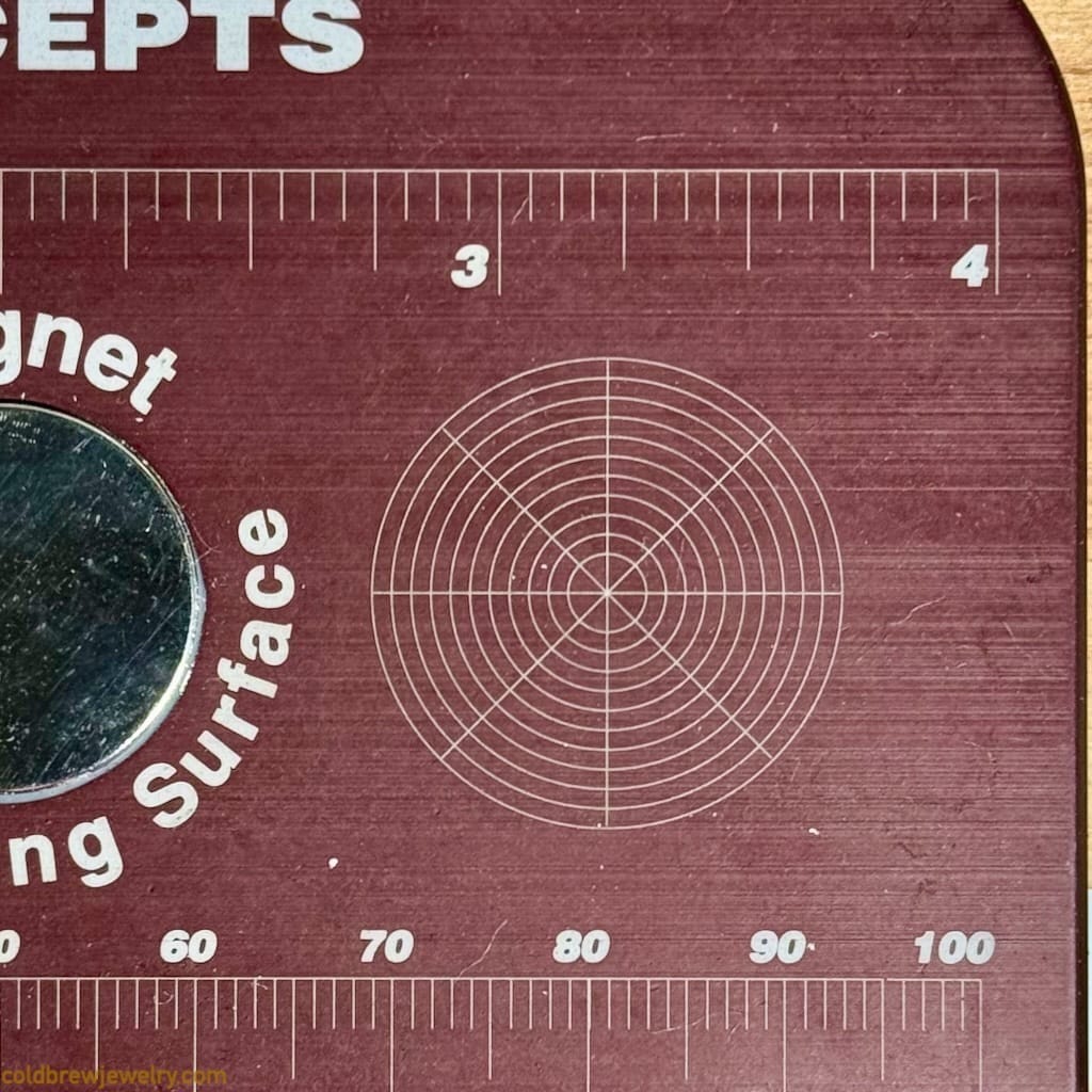
You can create it in any graphic editor and keep the printed version at hand. These patterns also help with marking out the circles into segments.
Alternative. You can use impression dies or die shot plates to make the shape perfectly round. You can find a good selection here, for example https://www.gemina.co.uk. The designs are usually a bit fancier than a simple circle, but they might work even better, depending on your design. You can use these with a hammer and a shot plate punch or hydraulic press.
Top basket setting
There are different ways of making a basket setting. At first, I wanted to make it out of a tube. For the top setting (2), the stone diameter is 5 mm, and I didn’t have a tube of this size, so I decided to make one. With silver, I wanted to go with an 18-gauge sheet to make the setting sturdy enough. The height of the setting was supposed to be around 3 mm. So, I needed to make two tube segments 1-1.2 mm high with a 1-0.6 mm gap between them. The idea was to make a segment about 3 mm high and then split it into two smaller segments.
I only had a small mandrel at hand to even out the tube. Long story short, it was hard to close such a small metal stripe into a ring for soldering. With a mandrel and a planishing hammer, I eventually managed to make it more or less round after soldering. But to be honest, it wasn’t good enough.
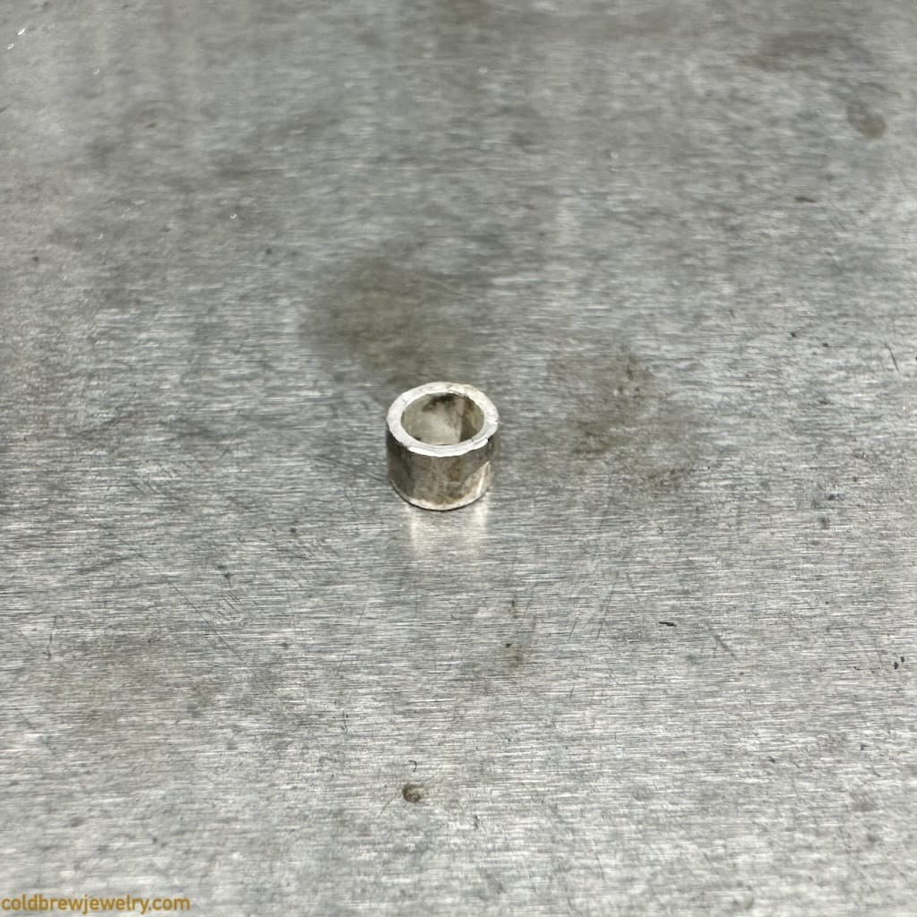
Alternative. I could have used a swage block to better form the tubing. But I think it would have taken more time, and the outcome wouldn’t have been much different from the round-wire basket setting.
At this point, I decided to pivot and make the basket using jump rings, which is more straightforward. I soldered two jump rings and an 8 mm piece of 18-gauge wire between them.
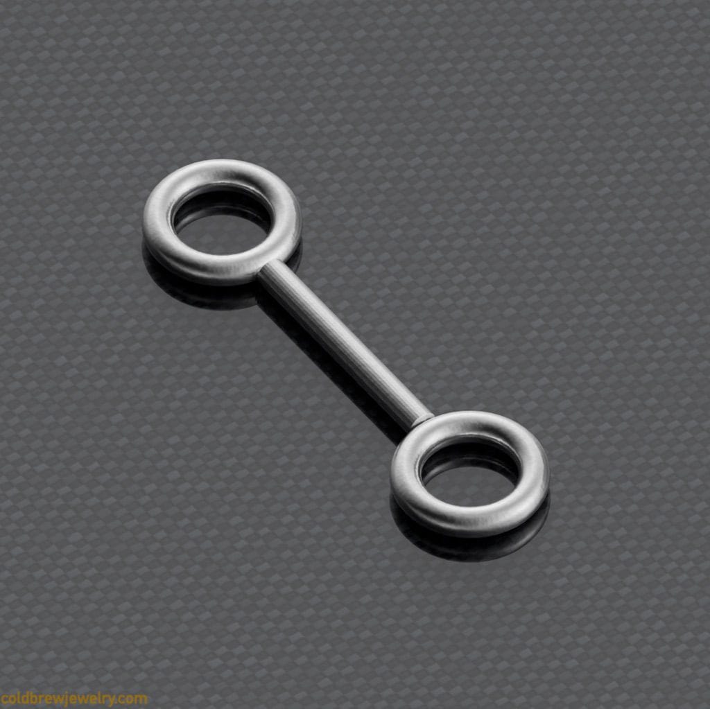
Then, I bent it in the middle so that one ring was on top of the other with a small gap. To do that, I put a small rod in the middle and bent around it to ensure the resulting loop between the rings could accommodate a jump ring that connects it to the rest of the piece. I put a 1 mm copper sheet between the rings to ensure I didn’t bend them too much.
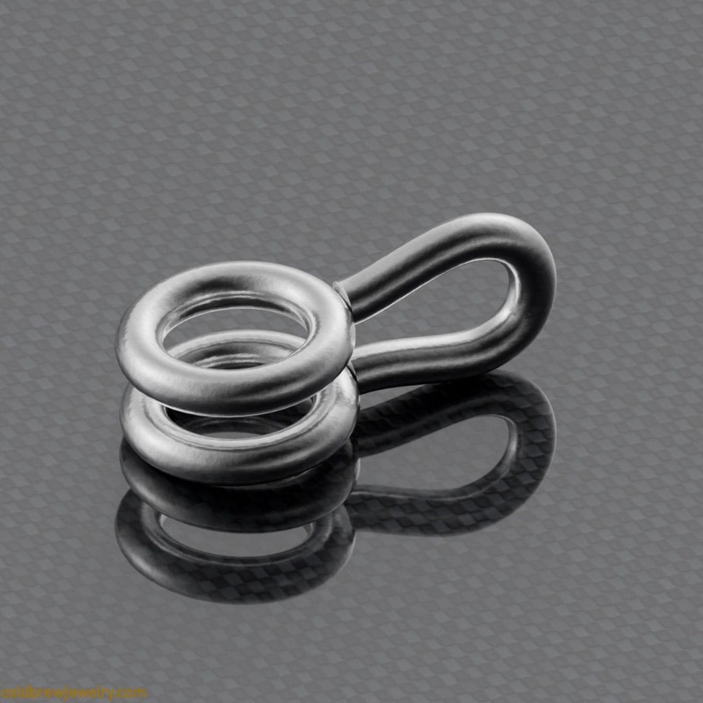
The next step was to mark the spots where the prongs would go. I’d use my dividing circle template, but because of the loop that was formed after bending, it wouldn’t lay flat. I ended up marking it by eye. But I should have been more precise, to be honest. The smaller the basket setting, the more apparent the small divergencies of the prongs from their proper positions are.
Alternative . I could have marked one ring before I bent the soldered basket. It was flat at that point and would have stayed perfectly on top of my circle template. Then, after bending the setting, I’d simply transfer the marks to the bottom ring or create a small notch with my saw and shape it further using a cylinder bur.
I cut four pieces of wire about 8 mm long. They could have been shorter, but I wanted to make the soldering easier for myself. Longer prongs let me position them almost in the middle when soldering to the jump rings, with the wire sticking evenly on both sides. This way, the wire won’t fall on either side when heated. You can argue that you could use a solder pick to adjust the prong as you go. And I agree. However, the prongs are very lightweight, and it can be hard to move them slightly without pushing them out of their place. It comes with practice, though. After soldering, I cut the prongs to the same length to leave enough space for the stone.
To conclude, don’t overcomplicate the architecture. Sometimes, a simple solution, like jump rings, works better and looks better than a more sophisticated one.
Bottom basket setting
I used a simple 18-gauge round wire this time to make the bottom setting (9). However, the stone’s diameter was 4 mm, so I needed to make a smaller setting. It’s not a big thing per se, but the smaller diameter makes the curve a bit tighter. This, in turn, means that soldering prongs just by placing them in the prepared groove might be more difficult since they’re more likely to slide down.
After learning the hard way by melting one setting, I decided to solder the prongs using a U-shaped wire.
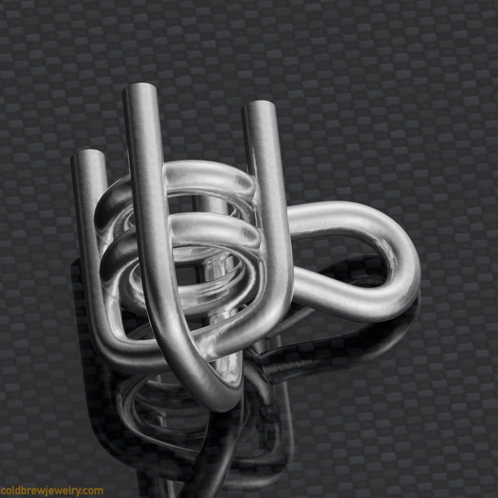
This way, the prongs sit tight against the setting and don’t move around when heated.
The bail with the jump ring
The bail looked like the easiest part to make. I pierced a 13 mm by 3 mm rhombus-shaped piece from a 20-gauge silver sheet. Then I bent it to a small ring and soldered it. Then, I squeezed it with parallel pliers to make it oval. The issue with this approach is that you can make it slightly 8-shaped by squeezing it too much. This is because the metal gets harder where it’s bent the most. In this case, it’s the sides of the bail. And in the middle, it’s still a bit softer. I tweaked it slightly with my small half-round pliers to make it even.
Alternative one. Instead of parallel pliers, I’d probably use regular flat-nose pliers to squeeze the ring into a bail. This way, the upper part would stay a bit larger to accommodate a chain, and the bottom part would be smaller since it only needs to fit a small jump ring. I also like the side look of such a shape better.
Alternative two. I haven’t tried it with bails, but bow-opening pliers can be used to make oval-shaped jump rings. These are reverse-action pliers for opening watch bows, but you can also use them for other things.
I also made a small jump ring and put it on the bail, which I’d solder later to the central round piece. Since this jump ring was supposed to hold the weight of the whole piece, I had to make the contact area for soldering as large as possible. I used a polishing point roughly the same diameter as the top setting (5 mm) to achieve that.
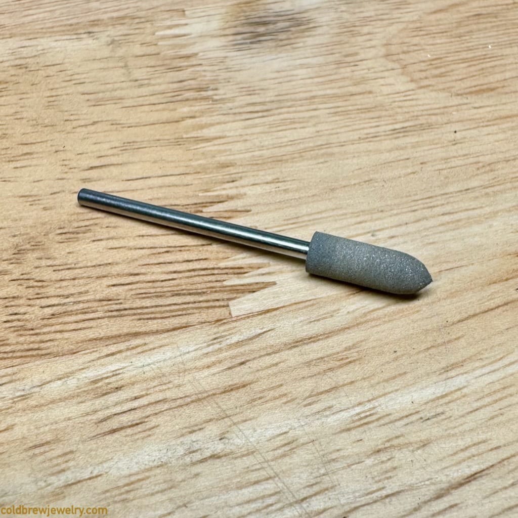
I filed one side of the jump ring flat with a needle file and then made it slightly curved using the polishing point.
But this bail isn’t what I included in the final design. I explain it below.
Soldering everything together
This is what I had so far:
- A bail with a jumping (1).
- A basket setting for the upper stone (2).
- A round piece in the center (3).
- Top wings with two tube settings (4).
- Connection piece (5) soldered together with bottom wings (6).
- Two segments (7, 8) at the bottom soldered together.
- A basket setting for the bottom stone (9) with a jump ring.
- Jump rings to connect basket settings to the rest of the piece (10).
It was time to put everything together. Since I had many soldered joints all done with hard solder, I had to switch to medium solder this time. I decided to solder these parts all at once: the top wings, the central round piece, the connection piece with the bottom wings, and the bottom segment.
But first, I adjusted the top wings and the connection piece with a polishing point to make the connection point slightly curved so it’d solder better to the central round part.
Here’s the order of soldering operations that I have followed so far:
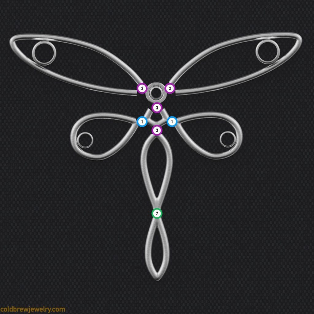
I wanted all of them on one plane and to stay put while soldering, so I decided to use holding clay. I used a flat acrylic piece to make a flat piece of clay on my soldering board. Then, I put all the parts on clay. Ideally, I’d use the same acrylic piece to push the parts into clay slightly. The issue was that all the parts were of different heights, so I had to judge by eye.
The clay takes some heat away from the metal, so you must ensure you’re using a hot enough flame. However, you’re still dealing with wire, so you have to be careful not to melt it. I used regular medium solder. But I also used Firescoff (a liquid fire scale protection) to cover all the parts just to be safe. There are alternatives to Firescoff, like Smart Flux from https://pepetools.com. I just happened to have the former at hand.
I’m mainly using butane torches currently. When I started soldering, I accidentally closed the air intake on my small butane torch and didn’t notice it. Thankfully, I stopped before heating everything for too long. As you probably know, heating fast to the right temperature is essential to avoid fire scale.
Ultimately, I soldered everything in one go. However, leveling parts by eye led to some minor misalignments that I had to clean up later.
Alternative. I could have soldered the parts using my Solderite board, but not in one go. Instead, I could have soldered the top wings to the central round part first, then the connection piece and the bottom wings to the bottom segments, and finally, the central part to the connection part. I could have used holding clay to cover the existing seams so they wouldn’t come apart.
Another solution that jewelers use, especially for mass production, is creating a soldering jig that holds everything in place. It can be made of brass, for instance. The goal is to create a “cage” around the elements to hold them steady. However, the parts need to be of a specific size to fit the jig.
Next, it was time to solder the bottom setting with a jump ring to the bottom segment.
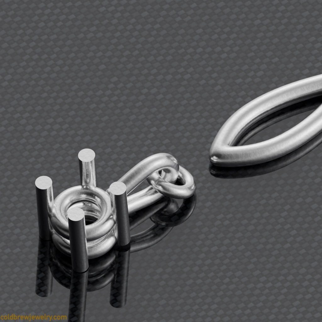
I had to keep the jump ring on the same plane as the rest of the piece. But as you can see, the loop on the setting wouldn’t let it lay flat on my soldering board, so I had to use soldering clay again. I pushed the setting into it slightly so that the jump ring sits level with the other part. I used paste solder this time. I directed my heat on the body segment (8) to avoid melting the jump ring, and everything went smoothly.
I did the same with the larger setting on the top. I used the same trick with clay but covered the top wings with it this time so they wouldn’t separate when heated. Because of that, heating the central round part (3) was hard. But ultimately, it went well. I used regular medium solder this time.
The final soldering operation was to attach the bail. I had to use the holding clay again to put the jump ring on the bail and the setting on the same level. I think some clay got between the two when I positioned the parts. So I applied too much heat, and, unfortunately, I ended up melting the bail and the jump ring.
I should have stopped after noticing that the solder didn’t flow as expected. Unfortunately, I wasn’t entirely focused and missed the moment.
After thinking it through, I replaced the bail with a simple jump ring. A thin bail might have looked a bit better, but the jump ring worked well enough.
Cleaning up and setting the stones
I was thrilled to finally have everything soldered together. I cleaned up with files and small pieces of sandpaper to get into corners and crevices. I also used polishing points here and there. After the clean-up, I pre-polished everything with a medium-aggressive polishing compound.
I had to set three 2 mm moissanites, two 3 mm citrines, a 5 mm, and a 4 mm cubic zirconias.
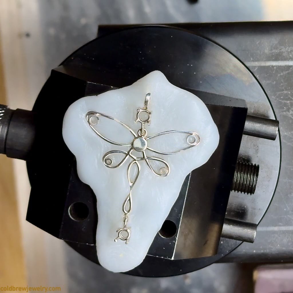
I put everything in thermoplastic to ensure I wouldn’t bend anything while setting. I started with tube settings for moissanites. I usually use a setting tool after cutting the seats.
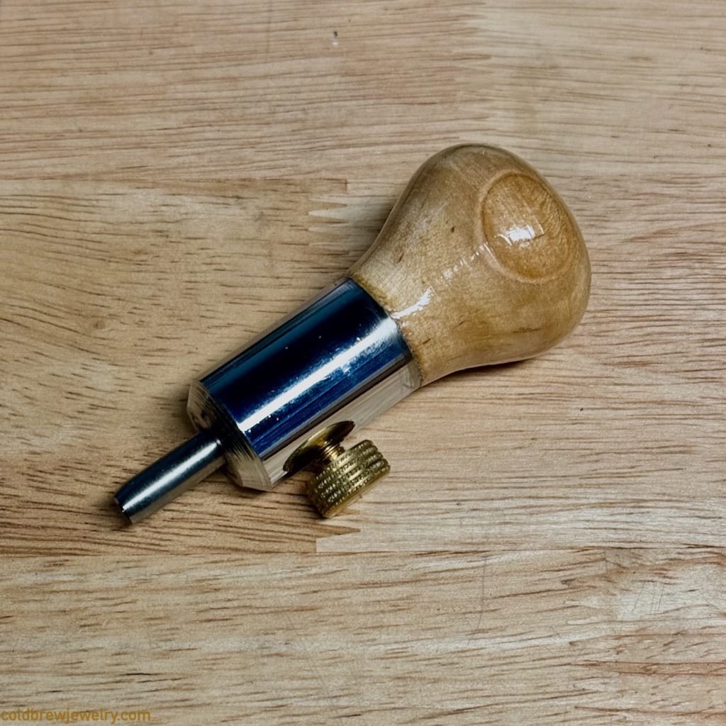
The only drawback is that a bit of burr accumulates around the top of the tube. I usually sand it lightly with either a piece of sandpaper or a polishing point to remove it.
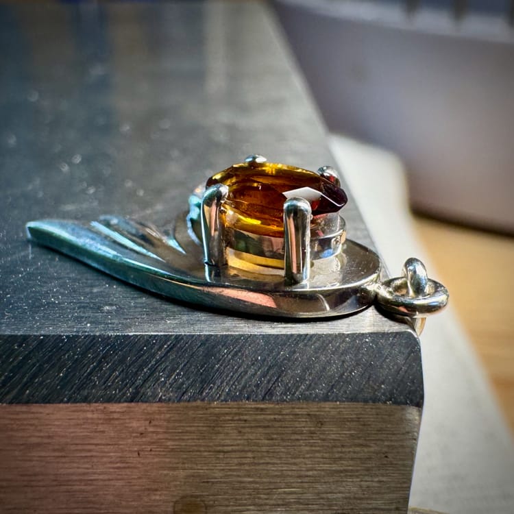
I flush-set the stone in the center, as described inPracticing flush-setting and engraving. Then, I had to set two CZs in their basket settings. In theory, it’s pretty simple. You cut the prongs with a hart bur, put in the stone, and close the prongs. In reality, you need to ensure you’re cutting in the right place to the correct depth.
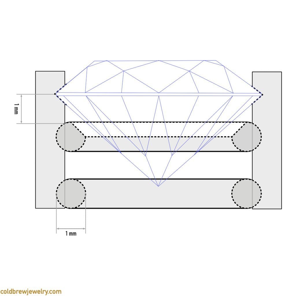
The outer diameter of the jump rings that form the setting should be the same as the stone. You usually cut about one-third of the thickness of the jump ring wire to place the prongs. Thus, the depth of the seat for the stone should be one-third of the wire thickness, too. As for the height, the goal is for the stone not to touch the base of the setting, the top jump ring, that is. It’s usually recommended to bevel the interior edge of the base with a ball bur. I usually mark the spot for the seat at a height equivalent to the wire thickness I used for the setting. So, if it’s an 18-gauge wire, I mark the prong about 1 mm above the top jump ring.
I also prefer to use my saw blade to put a small guiding nick first before I use the hart bur to cut the seat. One option is to use the bur slightly bigger than the gap between the prongs. This way, if the bur gets caught and runs around the prong, it would go around and mar the metal outside. The drawback is that, in this case, the bur has to be controlled more precisely so that it doesn’t accidentally touch other prongs. Also, unless you’re using a high-torque flex shaft or micro-motor, I suggest getting the but up to speed before touching the surface. Otherwise, there’s a good chance for it to get caught and run around your prong.
After closing the prongs, I slightly shaped them with my barrette needle file with a safe edge. Even though it’s called a “safe edge,” it might not be that safe for the softer stones. In this case, however, I had CZs that were pretty hard. But I always do it very carefully anyway to form the proper habit.
Again, having everything in thermo-plastic in my vise helped a lot with setting the stones. I could rotate my vise as needed and get to the right spot at the right angle. After setting all the stones, I did some minor clean-up where I had some marks on the metal and re-polished those spots with the same medium-aggressive compound, ensuring I didn’t accidentally touch the stones.
The last step was applying the final polish with a high-luster compound on a soft buff.
Final thoughts
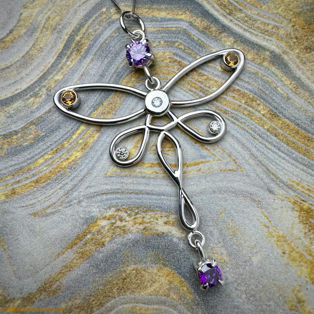
Overall, I’m pleased with the results. I even submitted the work to the “For the Love of Jewelry” challenge. However, there were some minor mistakes in the making process that I mentioned above. I’m also not one hundred percent happy with the prong positioning since they came out a bit asymmetrical. In hindsight, I can confidently say that the main reasons were stress and rushing.
One thing I often repeat on this blog is to keep the focus on the process and double-check everything before critical operations. It’s even more crucial for me since I don’t have the luxury of a dedicated studio, and sometimes it gets noisy around my workbench, so even the noise-canceling headphones don’t help. An excellent habit to master is to notice that you’re out of the flow or rushing before you ruin something and take a walk. Sometimes, I miss the moment and may melt something, for instance. Then, I finally went for a walk before continuing my work to start thinking clearly and picking the right solution.
If you have any questions, feel free to DM me on Instagram. Don’t forget to subscribe to my newsletter to be the first one to know when I publish a new post and receive some extra content!
Disclaimer: I’m not affiliated with any of the companies mentioned in this post. I included them because I either used their products myself or have seen them used by the jewelry community.

Member discussion